Comfort Requirements for Holographic Near-Eye Display - Dr. Weiner Lee
2021-01-22
Holographic Near-Eye Display is the development trend of AR/VR. From the user's perspective, the ultimate experience includes two aspects of comfort and immersion, as shown in Figure 1. Comfortable is related to wearability and visual comfort, which in turn include five subcategories: shape factor, speckle noise, eyebox, eye focus adjustment, and full color display. Immersive experiences are tied to FOV, the resolution of the display, and real-time interaction.
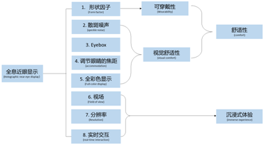
Fig. 1. Classification of holographic near eye display from a human-centered perspective.
In order to provide a comfortable and immersive experience, the hardware must be designed around the Human Visual System. The human eye is also a naturally evolved optical imaging system, in which light enters the eye through an iris that is adjustable in size, thereby controlling the flux of light entering the eye. The refraction of light through the cornea and lens in the retina to form a like, then the photoreceptor (photoreceptor) converts light signals into electrical signals, these electrical signals are then before in the retina to the brain through important signal processing (for example, the inhibition of horizontal cells), and finally by the brain based on visual clues to explain image and perception of three-dimensional space objects. We humans have binocular vision, with a horizontal field of view that can reach almost 200◦, with an overlapping binocular field of view of 120◦. Figure 2 shows the range of the horizontal Angle region of the human binocular visual system [1], while the vertical field of view is close to 130◦. In VR/AR field, there is a consensus that the minimum field of view for VR and AR should be 100◦ and 20◦[2] respectively. The density of photoreceptors varies significantly in the central and surrounding areas of the retina [3], and visual acuity is highly dependent on the density of photoreceptors. The center of the retina is a fovea region that has the highest photoreceptor density and 5.2◦ field of view (FOV), while outside the fovea, visual acuity begins to decline sharply. The uniform distribution of photoreceptors is a natural evolution that adjusts the on/off-axis resolution of this lens of the eye. Therefore, in order to make effective use of display pixels, a near-eye display must be optimized to provide a resolution that is consistent with the retinal's varying visual acuity. As a three-dimensional visual system, human eye provides depth cue, which can be further divided into physiological depth cue and psychological depth cue. Physiological depth cues include adjusting eye focal length, convergence, and motion parallax. Vergence means the rotation of the eyes in the opposite direction so that each eye converges on the object it wishes to see. Adjust "accommodation" means adjusting the light power in the eye's lens so that the eye can focus at different distances. For a near-eye display device, it is essential that a picture be displayed where the convergence distance equals the focal length that the eye can adjust. Otherwise, the conflict between the two will cause eye strain and discomfort. Psychological depth cues are activated by our experience of the world, for example, linear perspective, occlussion, shades, shadows, and the texture gradient embedded in the two-dimensional image [4]. Finally, the human eye is in constant motion to help capture the gaze and track visual stimuli. To ensure that images are always visible, the Exit Paramedics (Eyebox) to show the system need to be bigger than the eye movement (<= 12mm). In a display system, the product of eyebox and field of view (FOV) is finite and proportional to the product of the spatial bandwidth of the device. Therefore, enlarging the eyebox will reduce the field of view and vice versa. Although the spatial bandwidth product of the device can be improved by complex optical methods, the shape factor of the device is compromised. To alleviate this problem, common strategies include repeating the exit pupil on a matrix [5, 6, 7] and using eye-tracking devices. In order to maximize comfort and immersive experience, we had to build a display system that could meet the requirements of the optical structure and the human visual system. Next, we mainly introduce the shape factor and speckle noise of the holographic Near-eye Display comfort requirements and some solutions.
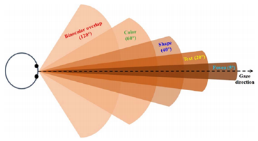
Figure 2. Visual field of the human eye.
1. Form Factor
The shape factor of a device determines its wearability. An ideal near-field display device must be light and compact, and can be worn all day like a regular eyewear, and the Google glasses are designed to fit this concept. Holographic near-eye display system has the advantage of small shape factor because of its simple optical path. The key optical element consists of only a coherent light source and a spatial light modulator (SLM). An SLM is essentially a pixelated display device that superposes a computer-generated hologram (CGH) onto the wavefront to modulate the amplitude or phase of the incident light. For an AR near-eye display system, an optical combiner must be integrated, and the shape factor of the system must be considered. Most early holographic near-eye display systems used a beam splitter as a photosynthetic drag to combine the light reflected from the SLM with the light transmitted from a real-world object, as shown in Figure 3. Modulated light from the SLM propagates through free space and is directed directly into the pupil of the eye or through an additional 4F system filter frequency [9, 10] or relay hologram (Fig. 3 (b))[8]. In order to realize a see-though electronic holography glass with a large eyebox, Ooi et al. also embedded multiple beam splitter into a unit [11].
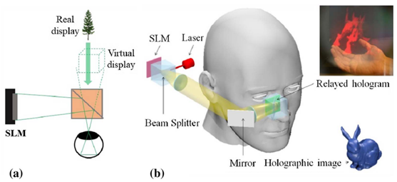
Fig. 3. Holographic see-through display using a beam splitter as an optical synthesizer. (a) Concept schematic, and (b) Relay and reflect the hologram to the eye through a 4F system.
Although widely used in proof-of-concept demonstrations, the shape factor beam splitter is not an ideal optical element considering its cube shape. Holographic Optical Element (HOE) could be an alternative because it is thin and flat and can function as a beam splitter. As an individual hologram, Hoe only modulates Bragg-matched Incident Light and does not match any light that does not. When implementing a holographic near-eye display system, HOE redirects light from SLM matching Bragg's law to the pupil of the eye and delivers real-world scenes to the human eye without additional light power. Moreover, the ability to record various wavelengths on HOE enables HOE to replace many traditional optical components, such as lenses and gratings, further reducing the size of the device.
Ando et al. first implemented HOE's near-eye display system in 1999 [14]. In a holographic near-eye display system, HOE is typically deployed in an off-axis device, as shown in Fig. 4 (a), and light from the SLM hits HOE at an oblique incidence Angle. HOE can be manufactured as a multifunctional device that integrates mirrors and lenses. For example, HOE can be used as an elliptical curved mirror [12,15] or as a beam expander [16]. Curved HOE can also reduce the shape factor and enlarge the FOV of the system to improve the imaging quality [17]. To further flatten the optical element and minimize the entire system, Martinez et al. substituted the off-axis lighting mode by combining HOE with a planar waveguide [18]. Fig. 4 (b) shows a classic device diagram in which light is coupled into (coupled into) and out of (coupled into) waveguide from HoE [13, 18, 19]. Note here that conventional HOE is generated by interference of two beams of light [20]. Due to the limited refractive index of holographic materials, traditional HOE can only be used for monochromatic light with narrow spectral bandwidth and narrow angular bandwidth during recording. Recent advances in metasurfaces [21, 22] and liquid crystals [23, 24] also provide corresponding alternative solutions. For example, Huang et al. used a metasurface structure as a CGH to demulex light with different wavelengths and polarization aspects, thus verifying a multicolor polarized near-eye display system [21, 22].
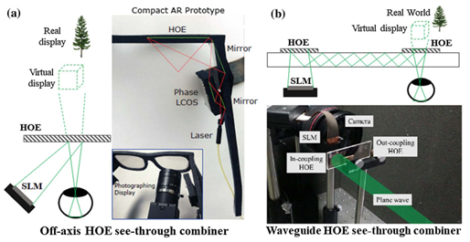
Fig. 4. The holographic optical element is used as a photosynthetic drag. (a) Off-axis HOE geometry [12], (b) Waveguide geometry [13].
2. Speckle Noise
Because of the requirement of coherence, holographic display usually uses laser as illumination source. However, the laser introduces speckle noise, a grainy pattern superimposed on top of the image. In order to suppress the speckle noise, we can adopt three strategies: superposition, spatial coherence construction, and temporal coherence destruction. In the stack-based approach, we first compute a series of holograms of the same 3D object by adding a statistically independent random phase to the complex amplitudes, and then continuously display them on the SLM during the eye response time, as shown in Fig. 5 (a). Due to the randomness in space, the average contrast of the combined speckle of the reconstructed 3D image is reduced, thus improving the image quality [23]. This method is mainly used in layered 3D models [8,24], because the calculation of holograms is relatively fast. Alternatively, we can use high speed speckle averaging devices such as rotary diffusers and vibration diffusers. Figure 5 (b) shows an example of a superposition of a rotating diffuser placed in front of a laser source. In this case, the speckle pattern is averaged over the frame time of the SLM. Speckle noise is generally caused by destructive spatial interference in the overlapping (imaging) point spread function [25]. We can actively manipulate spatial coherence structures to alleviate this problem. The most important method of this kind of strategy is complex amplitude modulation which can introduce constructive interference to the hologram. Instead of imposing a random phase on the wavefront, complex amplitude modulation uses a smooth phase map (i.e., a uniform phase) to carry out long phase interference between overlapping image points. To synthesize an expected complex amplitude field with phase-only or amplitude-only CGH, we can use analytic multiplexing [26,27], double-phase decomposition [28,29], double-amplitude decomposition [10], optimized phase recovery [30,31,32], and neural holography [33]. Fig. 5 (c) shows an example of decomposing the complex wavefront into two phases of the hologram and loading them on different regions of the SLM. This system uses a holographic raster filter to combine the hologram and reconstruct the 3D image with complex amplitude [10]. The main drawback of this method is that it requires the complex wavefront to contain only low frequencies, resulting in a small numerical aperture (NA) on the object side. This increases the depth of field (DOF) and thus weakens the focus cue. Makowski et al. provided an alternative solution that introduced a spatial segmentation between adjacent pixels to avoid the overlap of image space, thus eliminating false interference [25]. Finally, speckle noise can be suppressed by using a light source with lower temporal coherence. Partly coherent light sources, such as super light-emitting diodes (SLEDs) and micro LEDs (MLEDs), are used to suppress speckle noise [34]. An incoherent light can also be spatially shaped by using a spatial filter to preserve its temporal incoherence. For example, a spatially filtered LED light source has been verified to reduce speckle noise of holographic display [35, 36]. Recently, Olwal et al. extended this method to an LED array and verified high quality 3D holography [37]. The disadvantages of using partially coherent light include reduced sharpness and shortened depth range. However, the latter can extend the depth range by reconstructing the image very close to the SLM and using either a tunable lens [38] or an eyepiece [39].
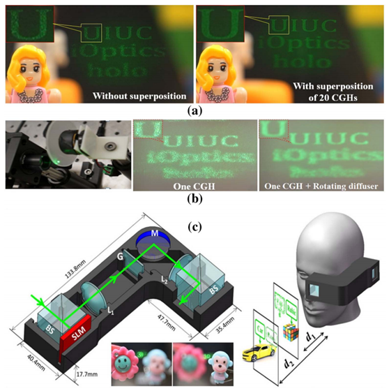
Fig. 5. Three methods of speckle noise suppression :(a) overlapping multiple CGHs, (b) rotating diffuser, and (c) complex amplitude modulation with a single CGH.
This paper introduces the requirement of shape factor of near eye display system and some common methods to reduce speckle noise. Next, we'll talk about eyebox, eyebox accommodation and full colour display.
reference
1.B. C. Kress, “Human factors,” in Optical Architectures for Augmented-, Virtual-, and Mixed-Reality Headsets (SPIE, 2010).
2.B. Kress and T. Starner, “A review of head-mounted displays (HMD) technologies and applications for consumer electronics,” Proc. SPIE 8720, 87200A (2013).
3.C. A. Curcio, K. R. Sloan, R. E. Kalina, and A. E. Hendrickson, “Human photoreceptor topography,” J. Comp. Neurol. 292, 497–523 (1990).
4.B. Lee, “Three-dimensional displays, past and present,” Phys. Today 66(4), 36–41 (2013).
5.H. Urey and K. D. Powell, “Microlens-array-based exit-pupil expander for full-color displays,” Appl. Opt. 44, 4930–4936 (2005).
6.T. Levola, “Diffractive optics for virtual reality displays,” J. Soc. Inf. Disp. 14, 467–475 (2006).
7.C. Yu, Y. Peng, Q. Zhao, H. Li, and X. Liu, “Highly efficient waveguide display with space-variant volume holographic gratings,” Appl. Opt. 56, 9390–9397 (2017).
8.J.-S. Chen and D. P. Chu, “Improved layer-based method for rapid hologram generation and real-time interactive holographic display applications,” Opt. Express 23, 18143–18155 (2015).
9.E. Moon, M. Kim, J. Roh, H. Kim, and J. Hahn, “Holographic head-mounted display with RGB light emitting diode light source,” Opt. Express 22, 6526–6534 (2014).
10.Q. Gao, J. Liu, X. Duan, T. Zhao, X. Li, and P. Liu, “Compact see-through 3D head-mounted display based on wavefront modulation with holographic grating filter,” Opt. Express 25, 8412–8424 (2017).
11.C. W. Ooi, N. Muramatsu, and Y. Ochiai, “Eholo glass: electroholography glass. a lensless approach to holographic augmented reality near-eye display,” in SIGGRAPH Asia 2018 Technical Briefs (ACM, 2018), p. 31.
12.A. Maimone, A. Georgiou, and J. S. Kollin, “Holographic near-eye displays for virtual and augmented reality,” ACM Trans. Graph. 36, 85 (2017).
13.H.-J. Yeom, H.-J. Kim, S.-B. Kim, H. Zhang, B. Li, Y.-M. Ji, S.-H. Kim, and J.-H. Park, “3D holographic head mounted display using holographic optical elements with astigmatism aberration compensation,” Opt. Express 23, 32025–32034 (2015).
14.T. Ando, T. Matsumoto, H. Takahashi, and E. Shimizu, “Head mounted display for mixed reality using holographic optical elements,” Mem. Fac. Eng. 40, 1–6 (1999).
15.G. Li, D. Lee, Y. Jeong, J. Cho, and B. Lee, “Holographic display for see-through augmented reality using mirror-lens holographic optical element,” Opt. Lett. 41, 2486–2489 (2016).
16.P. Zhou, Y. Li, S. Liu, and Y. Su, “Compact design for optical-see-through holographic displays employing holographic optical elements,” Opt. Express 26, 22866–22876 (2018).
17.C. Martinez, V. Krotov, B. Meynard, and D. Fowler, “See-through holographic retinal projection display concept,” Optica 5, 1200–1209 (2018).
18.W.-K. Lin, O. Matoba, B.-S. Lin, and W.-C. Su, “Astigmatism correction and quality optimization of computer-generated holograms for holographic waveguide displays,” Opt. Express 28, 5519–5527 (2020).
19.J. Xiao, J. Liu, Z. Lv, X. Shi, and J. Han, “On-axis near-eye display system based on directional scattering holographic waveguide and curved goggle,” Opt. Express 27, 1683–1692 (2019).
20.“Holographic optical elements and application,” IntechOpen, https://www.intechopen.com/books/holographic-materials-andoptical-systems/holographic-optical-elements-and-application.
21.Z. Huang, D. L. Marks, and D. R. Smith, “Out-of-plane computer-generated multicolor waveguide holography,” Optica 6, 119–124 (2019).
22.Z. Huang, D. L. Marks, and D. R. Smith, “Polarization-selective waveguide holography in the visible spectrum,” Opt. Express 27, 35631–35645 (2019).
23.J. Amako, H. Miura, and T. Sonehara, “Speckle-noise reduction on kinoform reconstruction using a phase-only spatial light modulator,” Appl. Opt. 34, 3165–3171 (1995).
24.C. Chang, W. Cui, and L. Gao, “Holographic multiplane near-eye display based on amplitude-only wavefront modulation,” Opt. Express 27, 30960–30970 (2019).
25.M. Makowski, “Minimized speckle noise in lens-less holographic projection by pixel separation,” Opt. Express 21, 29205–29216 (2013).
26.X. Li, J. Liu, J. Jia, Y. Pan, and Y. Wang, “3D dynamic holographic display by modulating complex amplitude experimentally,” Opt. Express 21, 20577–20587 (2013).
27.G. Xue, J. Liu, X. Li, J. Jia, Z. Zhang, B. Hu, and Y. Wang, “Multiplexing encoding method for full-color dynamic 3D holographic display,” Opt. Express 22, 18473–18482 (2014).
28.Y. Qi, C. Chang, and J. Xia, “Speckleless holographic display by complex modulation based on double-phase method,” Opt. Express 24, 30368–30378 (2016).
29.C. Chang, Y. Qi, J. Wu, J. Xia, and S. Nie, “Speckle reduced lensless holographic projection from phase-only computer-generatedhologram,” Opt. Express 25, 6568–6580 (2017).
30.C. Chang, J. Xia, L. Yang, W. Lei, Z. Yang, and J. Chen, “Specklesuppressed phase-only holographic three-dimensional display based on double-constraint Gerchberg–Saxton algorithm,” Appl. Opt. 54, 6994–7001 (2015).
31.P. Sun, S. Chang, S. Liu, X. Tao, C. Wang, and Z. Zheng, “Holographic near-eye display system based on double-convergence light Gerchberg-Saxton algorithm,” Opt. Express 26, 10140–10151 (2018).
32.P. Chakravarthula, Y. Peng, J. Kollin, H. Fuchs, and F. Heide, “Wirtinger holography for near-eye displays,” ACM Trans. Graph. 38, 213 (2019).
33.Y. Peng, S. Choi, N. Pandmanaban, and G. Wetzstein, “Neural holography with camera-in-the-loop training,” in SIGGRAPH Asia (ACM, 2020).
34.Y. Deng and D. Chu, “Coherence properties of different light sources and their effect on the image sharpness and speckle of holographic displays,” Sci. Rep. 7, 5893 (2017).
35.T. Kozacki and M. Chlipala, “Color ho
