Review of VRAR Display devices - Dr
2021-11-09
A brief introduction to VRAR common display technology
The display engine is the primary optical component of any HMD display architecture, but it cannot function alone and needs to be combined with optical components (free-form surfaces or waveguides) to form the optical display engine to achieve pupil dilation and other effects.
Therefore, the display engine has three main functions:
1. Produce the desired image (usually in the angular spectrum, i.e. the far field),
2. Provide an exit pupil overlapping with the incident pupil of the optical element.
3. Adjust the width to height ratio of exit pupil properly to meet the requirements of pupil expansion scheme, thus creating the required size of the glasses case.
Therefore, the design of the display engine needs to be done together with the design of the optical elements as a global system optimization, especially when using waveguide schemes.
The display engine can create square or circular exit pupils if the optical element can perform 2D exit pupil dilation, and rectangular (or elliptical) exit pupils if the optical element expands in only one direction. In some cases, the optical display engine may create a variety of spatially reusable exit lenses in different colors or fields to provide other functions, such as multiple focal planes (two in Magic Leap One).
Optical display engines are typically built around three different parts:
1. Light source (for non-luminous display panel),
2. Display panel (or micro display) or scanner,
3. Relay optical devices (or imaging optical devices) form composite optical devices.
Currently, there are two types of screen display systems available for VR and AR: direct vision display and micro display. The former is mostly used in smart phones (LTPS-LCD, IPS-LCD or AMOLED) with a size range of 3.5 -- 5.5 "and a resolution range of 500 -- 1500 PPI. Miniature display panels, such as high temperature polysilicon LCD (HTPS-LCD) and silicon-based liquid crystal (LCoS) based on silicon backboard, silicon-based AMOLED (μ-AMOLED) or microinorganic light-emitting diode (μLED) panels and digital Light processing (DLP) MEMS panels size 0.2 to 1.0 inches, The resolution is 2000-5000 PPI.
Tiny displays that use an external light source (as well as a rear backlight or a front light source) are already used in smart glasses and AR headsets, such as HPSS-LCD (Google Glass V2), LCoS (Lumus, HoloLens V1, Magic Leap One) or DLP (Digilens, Avegant). Self-luminescent microdisplay panels are also widely used, such as silicon-based OLED displays (ODG R9, Zeiss Tooz smart glasses). Higher-brightness μLED microdisplays promise to revolutionize AR optical engines by providing the required brightness (mega nits) and contrast to compete with outdoor sunlight without having to provide a cumbersome light source system. It's worth noting that μLED microdisplays are very different from their larger counterparts. Mini-leds look directly at display panels, such as TV panels, and their LED sizes are still large (100 to 1000 microns). However, the miniaturization of μLED is limited by the technology. When the size is reduced below 10 microns (1200 PPI or more), the edge recombination effect greatly reduces the efficiency, so LED structures must be grown in THREE dimensions, such as nanorods or other 3D structures. At present, the huge transfer of μLED is still the technical bottleneck of the industry. Figure 1 shows some of these panels that are currently used in many AR/VR products.
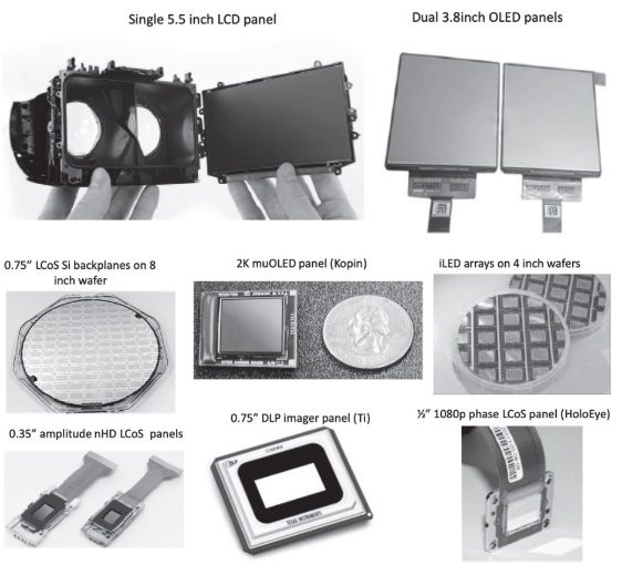
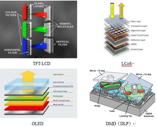
Figure 1 The various display panels currently used in AR/VR products
Polarization and emission Angle are also important features of microdisplay panels (spontaneous or non-spontaneous) because they directly affect the brightness of the image and the perceived size of the eye box. For example, LCoS and LCD-based phase panels are polarized display panels (and therefore require single-polarized light sources), while LED, μ-OLED or DLP panels and MEMS scanners are non-polarized displays and can therefore use light sources of all polarized states. Using a single polarization (linear or circular) doesn't necessarily mean that the light source brightness lower half, because there have been a very effective polarization recovery program, and can convert 20% to 30% of the polarization error, thereby to increase the efficiency of polarization to 70-80% (especially in mini projector lighting engine used in free space lighting architecture).
Finally, the efficiency of tiny display panels is crucial for wearable display applications. Color sequential LCoS displays are nearly 50% efficient, while color filter LCoS displays are only about 15% efficient, and LTPS LCD microdisplay panels (Kopin) are usually only 3-4% efficient. DLP MEMS displays are the most efficient displays and therefore can provide the highest brightness (e.g. Digilens Moto-HUD HMD). Although color timing displays are more efficient than color filter displays. But the former produces a color break when the user's head moves quickly. LCD and OLED panels are typically used as true RGB color panels, while LCoS and DLP panels are typically displayed in color sequence.
Panel response time is also an important parameter, especially when a display needs to be driven at a higher refresh rate to provide more functionality, such as in multi-focal plane displays. DLP is currently the fastest response time display and can therefore be used in such architectures (e.g. Avegant Multifocus AR HMD).
μLED due to its high brightness, high efficiency, high reliability and small pixels, silicon-based inorganic LED arrays (commonly known as μLED micro displays) have attracted a lot of attention. Firstly, wearable displays, Examples are smartwatches (Apple acquired LuxVue in 2014) or display options for AR devices (InfiniLed acquired by Facebook/Oculus in 2015, Google acquired Glo Inc in 2016. Mojo-vision in 2019 and Aledia SaRL in 2017 for $4.5 billion). Due to a lattice mismatch between the LED material (AlGaN/InGaN/GaN) and Si, leds must be grown on a conventional sapphire substrate, then cut into small pieces, and then "picked up and placed" on the final Si substrate (or glass substrate). Although μLED Si backplanes may be similar to LCoS Si backplanes, the transfer process is often the bottleneck for μLED micro displays, which is time-consuming and prone to yield problems. But μLED, a startup, has recently developed an interesting and novel transfer technology to alleviate this problem.
The technology roadmap for μLED micro displays shows three successive generations of architecture, each more efficient than the last and therefore brighter:
- First generation, UV μLED array with phosphor layer and color filter pixel on Si backplane,
- Second generation, UV μLED array with phosphor layer and quantum dot color conversion pixel on Si backplane,
- Third generation, grow RGB μLED directly on Si backplane.
μLED arrays can also be picked up and placed on transparent LTPS glass substrates such as Glo, Lumiode, Plessey. However, several companies (Aledia, Plessey, etc.) continue to pursue direct growth of leds on Si substrates.
From the current state of the industry, it is worth noting that traditional μ-OLED has shifted to r&d and customized production specifically for AR applications, such as bidirectional OLED panels (integrating RGB display pixels and IR sensor pixels in the same array) and ultra-low power consumption, Monochrome OLED panels produced by Fraunhofer Institute (Dresden, Germany). Bidirectional OLED panels are very effective for AR displays, on-axis eye-tracking applications, and other dual imaging/display applications. μOLED panels up to 3147 PPI have been used in small VR/AR panels, such as Luci (Santa Clara, CA, 2019), Nreal, etc. BOE also launched over 5000PPI μOLED products in 2020.
High-end AR, VR and MR headsets require improved angular resolution to match the acuity of the human eye. Optical offset can greatly increase the angular resolution of the central concave region without increasing the number of pixels in the display panel.
Another technology that has been used as a DLP display engine is Wobulation (the DLP display technology introduced by TI in the mid 90's and thriving). This technique also increases the refresh rate of the display and slightly changes the Angle of the display to show pixels between pixels (especially suitable for immersive display configurations).
The original Wobulation technology used a rotating wedge or glass to create a slight angular offset that was synchronized with the display refresh rate. A variety of other mechanical technologies have been used since then, and more recently, non-mobile solid-state wobulation technologies have been introduced, such as LC Wobulators (as in tunable liquid prisms), switchable PDLC prisms, switchable window beps (Optotune AG), and even phased array oscillators.
Another interesting wobulation technique can switch leds without any adjustable components, requiring only multiple light sources (LED or laser), as shown in Figure 2 (a very compact optical oscillator architecture).
Although mechanically mobile and steerable wobulation technology can work on any type of display (provided their refresh rate is high enough), light source switching wobulation technology is limited to non-luminous displays, such as DLP, HTPS, LCD and LCoS displays.
Optical Wobulation technology can effectively increase angular resolution (PPD) without increasing the number of pixels in the display panel. However, this technology is limited to display architectures with potentially high refresh rates, such as DLP and fast LCoS displays.
Another very compact wobble technique would use multiple mirrors in a single DLP array, but this greatly increases the difficulty of designing and manufacturing MEMS DLP arrays. This results in the most compact optical wobulation architecture.
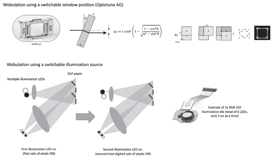
Figure 2. Optical oscillation using mechanical motion or multiple light sources.
Optical foveation and optical wobulation can be combined to increase the number of pixels, thus providing a high resolution perception for the viewer without increasing the physical number of pixels in the display. However, optical wobulation is not necessarily a form of optical foveation. If wobulation is fixation-local control and can manipulate a larger portion of the pixels in an immersive FOV, it can evolve into an optical FOveation architecture.
Today, scan display engines are used in various HMD systems. The main advantages of such a system are small size (because there is no object plane in the display panel, so it is not explicitly limited by the law of optical expansion), high brightness and efficiency of the laser light source, high contrast, and "real-time" optical foveation, since pixels can be turned on in any custom way in the pixel space, So it can be reconfigured using fixation tracking.
Early VR and AR systems used miniature cathode ray tubes (CRTS) display technology (technically scanners) (e.g. Sword of Damocles, 1968). They are still used in monochrome mode for certain high-end military AR helmets (the integrated Helmet and Display Targeting System (IHADSS) for the Apache AH-64E helicopter pilot helmet) with unique brightness and contrast. Figure 3 summarizes the various scanning display technologies studied so far.
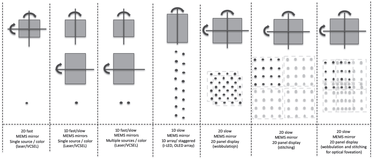
FIG. 3 Various NTE image scanning display implementations of a single 2D or dual 1D MEMS mirror scanner
Other scanning display technologies, such as fiber optic scanners, integrated electro-optic scanners, acoustooptic modulators (AOM), phased array beam guides and surface acoustic wave (SAW) scanners. Figure 6 depicts some of these scanners, such as the final product (one-dimensional / 2D)

MEMS scanner) and R&D prototype (fiber optic scanner and SAW scanner). Most scanner-based optical engines lack exit pupil size (eye box size) and therefore require a complex optical architecture to expand/replicate or guide the exit pupil to the user's eye.
Figure 4. Some of the laser scanner implementations used in the product and prototype.
Laser-based phase panel display engines (i.e., dynamic holographic projectors) have recently entered the market through automotive HUDs due to their high brightness (light is redirected by diffraction rather than absorbed like traditional panels).
They have also recently been used to design interesting HMD architecture prototypes that can provide a per-pixel depth display, effectively addressing VAC. Panels can come from LCoS platforms (HoloEye, Jasper, Himax, etc.) to MEMS pillar platforms (Ti).
Synthetic holograms are often called computer-generated holograms (CGH). Static CGH has been designed and used for a variety of applications for decades, such as structural light sources for depth cameras (Kinect 360 (2009) and iPhone X (2018)) or engineered diffusers; Custom pattern projectors such as "virtual keyboard" interface projectors (Canesta 2002 and Celluon 2006); Or as a simpler laser pointer pattern projector. The implementation of dynamic CGH is still under development and has broad prospects for AR/VR/MR displays.
Diffraction phase panels can operate in a variety of modes, from far-field 2D displays (Fourier CGH) to near-field 2D or 3D displays (Fresnel CGH). Iterative algorithms such as the Iterative Fourier Transform Algorithm (IFTA) can be used to compute Fourier or Fresnel holograms. However, due to the obvious time consuming aspects of CGH iterative optimization, direct calculation methods are preferred, such as phase superposition of spherical wavefronts emanating from all pixels in a 3D pixel configuration representing the 3D object to be displayed.
Figure 5 shows some of HoloEye's (Germany) popular diffraction phase panels and VividQ (UK) prototype head displays, as well as a typical Fresnel CGH mode and 3D reconstruction, showing the different depths of the image, thus addressing VAC.

Figure 5. Diffraction phase panel and HMD operation.
Today, the implementation of HMD products is limited by some unresolved challenges in real-time computation of CGH patterns (even with non-iterative methods), reduced laser speckle, smaller exit pupil, and a lack of available low-cost/high-quality phase panels. However, phase panel-based dynamic holographic displays remain the ideal architectural choice for future small size, high FOV, high brightness and true per-pixel depth HMD.
Common problems related to display technology in VRAR
1. Screen effect
If the MTF of the display system is able to parse pixels well, especially in panel-based VR systems, users may see pixels interlaced, which can create a parasitic and annoying "window screen effect". The gap can be closed either by reducing pixel spacing (the pixel gap on OLED panels is smaller than that on LCD panels) or by intentionally lowering the MTF of the system (which is difficult to do when it affects display performance and quality).
The screen effect can be reduced by adjusting the MTF of the collimating lens in the VR system or the MTF of the display engine in the AR system (see Figure 6). Imaging systems with reduced MTF (MTF # 2) can smooth virtual images in angular space, although physical display pixels will still show screens and virtual images generated through a high quality lens (MTF # 1) will also be displayed. Optical components cannot further solve the problem of pixel spacing.
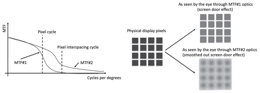
Figure 6. Adjust MTF of optical device to smooth window screen effect.
2. Sawtooth effect
Direct vision displays and miniature display panels are usually made of pixels arranged in a grid. When displaying a diagonal or curve, you actually have to draw a curve with a square block placed along the grid to produce a sawtooth. Anything other than a straight line will naturally show the basic shape of the pixels and grid of pixels. Increasing pixel density reduces jagging. Anti-aliasing can also reduce perceived aliasing by using pixels of different colors along the edges of the lines to create smoother lines. Serrations (for example, rapid changes in the configuration of fast-moving pixels that might indicate them) are particularly annoying in the peripheral areas of an immersive display because humans are particularly sensitive to peripheral movement.
3. Motion blur
Motion blur is also detrimental to high resolution virtual image perception. A refresh rate of 90 Hz and a very fast response time between 3 -- 6ms will greatly reduce motion blur.
4. Mura effect
Mura effect or "turbidity" is a term commonly used to describe an uneven display caused by an imperfect light source or uneven screen. These effects may show up in areas or individual pixels that are darker or lighter, have poor contrast or only deviate from the overall image. In general, these effects are particularly pronounced at low gray levels. Generally speaking, the Mura effect is the basic design feature of current LCD display panels. The Mura effect can also be seen in OLED panel-based displays. Immersive displays in VR enhance the perception of Mura effects. In AR head displays, the Mura effect is perceived much less than in VR systems because the transparent background color and uniformity changes as the head moves through the scene. Figure 7 illustrates the various effects of the display technology itself.
Figure 7 sand-window effect, Mura effect, showing jagged and motion blur
Crepuscular rays are also common effects of the display technology itself. Crepuscular rays have streaks of light, which can be caused by a variety of factors, such as diffusion, diffraction, or even Fresnel lens rings. In VR systems, this phenomenon is even more pronounced in dark fields with bright white text.

The human eye has very high visual acuity and can resolve features well below the minimum radian scale, at least all images that can be provided by a display engine using today's finite pixel density display technology. Therefore, operating on the MTF of the display engine can provide a good way to smooth the screen effect in an immersive space. However, it is not easy to effectively adjust the MTF of projected optics so as to maintain good MTF over the pixel period while omitting smaller features.
Third, summary
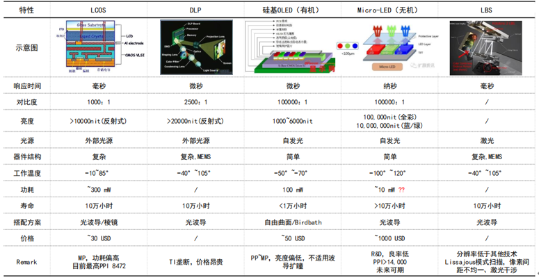
In summary, this paper introduces several common display technologies used in VRAR headdisplay. Among them, LTPS-LCD is still the mainstream for VR headdisplay, and PPI will exceed 1500PPI. However, with the pursuit of lightweight and large field Angle, μOLED or flexible OLED will gradually be used. In terms of AR, LCoS and silicon-based OLED are the mainstream AR optical machines on the market at present. LCoS is suitable for waveguide and prism optical schemes, with mature process and reasonable price, and currently has a high market share. Silicon-based OLED has relatively low brightness and is suitable for optical schemes without pupil expansion, and has the highest cagR. LBS applied to Hololens2 optical waveguide scheme, the picture display quality is not high; Micro-led is the most promising AR optical machine technology in the industry, with a promising future.
Annex 1: SUMMARY of AR display devices
LCoS and silicon-based OLED are the mainstream AR optical machines on the market at present. LCoS is suitable for waveguide and prism optical schemes, with mature process and reasonable price, and currently has a high market share. Silicon-based OLED has relatively low brightness and is suitable for optical schemes without pupil expansion, and has the highest cagR. LBS applied to Hololens2 optical waveguide scheme, the picture display quality is not high; Micro-led is the most promising AR optical machine technology in the industry, with a promising future.
reference
[1] L. Rao, S. He, and S.-T. Wu, “Blue-Phase Liquid Crystals for Reflective Projection Displays,” J. Display Technol. 8(10), (2012).
[2] “Understanding Trade-offs in Micro-display and Direct-view VR headsets designs,” Insight Media Display Intelligence report (2017).
[3] Z. Liu, W. C. Chong, K. M. Wong, and K. M. Lau, “GaN-based LED micro-displays for wearable applications,” Microelectronic Eng. 148, 98–103 (2015).
[4] B. T. Schowengerdt, M. Murari, and E. J. Seibel, “Volumetric Display using Scanned Fiber Array,” SID 10 Digest 653 (2010).
[34] S. Jolly, N. Savidis, B. Datta, D. Smalley, and V. M. Bove, Jr., “Near-to-eye electroholography via guided-wave acousto-optics for augmented reality,” Proc. SPIE 10127 (2017).
[35] E. Zschau, R. Missbach, A. Schwerdtner, and H. Stolle, “Generation, encoding and presentation of content on holographic displays in real time,” Proc. SPIE 7690, 76900E (2010)
[36] J. Kollin, A. Georgiu, and A. Maimone, “Holographic near-eye displays for virtual and augmented reality,” ACM Trans. Graphic 36(4), 1–16 (2017).
[88] B. Kress and P. Meyrueis, Applied Digital Optics: From Microoptics to Nanophotonics, 1st edition, John Wiley and Sons, New York (2007).
